Steelmaking
Steelmaking
Hot metal and crude steel production
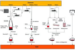
Steel is mainly produced via two different process routes: the path from “iron ore to steel” and the path from “scrap to steel”. With the iron-ore based route, hot metal is mostly produced from iron oxide ores in blast furnaces, and more rarely in smelting reduction plants, and is processed to make crude steel in oxygen converters. Sponge iron (direct reduced iron, DRI; hot briquetted iron, HBI) produced from iron ore in direct reduction plants is converted to crude steel in electric arc furnaces. With the scrap-based route, crude steel is produced by recycling steel scrap in electric arc furnaces.
Steel is a modern material that offers versatile use and is still undergoing continuous further development. Thus the European steel industry produces about 2,500 standardised steels as well as a wide range of customer-specific steel grades. Each year, the compositions of about 100 steel grades are adapted to the increasing demands. Up to 30 entirely new steel grades are developed annually. Steel is used in almost all important industrial sectors, e.g. apparatus and machine construction, bridge construction, structural engineering, energy and environmental technology, transport and traffic, the packaging industry, etc.
Levels of regional and national steel production and steel use depend on population numbers and on the state of technical and economic development. World crude steel production rose from 40 million tonnes in 1900 to about 1.55 billion tonnes in 2012. In the international ranking Germany is in seventh place with 42.7 million tonnes annual production, while China is the world’s largest steel producer with 716.5 million tonnes. Steel is the number one material – and will remain so in this century.
Hot metal production in blast furnaces
In the case of the process route via the blast furnace, liquid hot metal is initially produced from iron ores, additives as well as coke and other reducing agents (such as coal, oil or gas). The hot metal is converted to crude steel in the downstream oxygen converter steelworks.
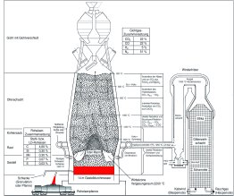
A blast furnace is a shaft-shaped aggregate that operates according to the “counter-current streams” principle. The coarse-grained input materials, coke and the burden (iron ore + additives) are charged from top via the furnace throat, while the reducing gas flows in the opposite direction of the sinking bulk material from the lower part of the blast furnace.
Preparation of blast furnace charge materials
Preparation of the charge materials is important for ensuring an even gas flow throughout the column of bulk material in the blast furnace. Iron ores are used in the form of lump ores, sinter and pellets. Lump ores are natural useable coarse grained ores extracted at iron ores mines. Preparation and enrichment processes undertaken at the iron ore mines to increase the iron content, however, result in increasingly fine grained ores that must be granulated. This is achieved by means of pelletising and sintering.
In the case of pelletising, the finest of ores (the pellet feed) and concentrate with grain sizes of well below 1 mm are formed into small balls with diameters of about 10 – 15 mm. For this purpose, the ore mixture is moistened and a binding agent added. The “green pellets” are then formed in rotary drums or on rotary tables. These green pellets are dried and burned for strengthening at temperatures of over 1000°C. This can take place in shaft furnaces, rotary kilns or on a travelling grate. Pelletising plants are generally located at the iron ore producers.
Sintering (caking) is carried out using strand sintering plants with strand widths of over 4 m and strand lengths of over 100 m. During the sintering process a mixture of ore fines with coke breeze, additives, recycling materials and return fines placed on a circulating grid, called the sintering strand, and the coke breeze on the surface is ignited in an ignition furnace using gas flames. A flow of gas or air is passed through the mixture from above by means of suction applied from below. A hot front thus passes over the band length of the approx. 500 mm layer, causing a caking of the mixture to create coarse lumps of ore. Sinter plants are located on the grounds of steel producers, near the blast furnaces.
All iron ores contain oxygen that must be removed through reduction in the blast furnace process. Carbon is used for this process. The most important carbon carrier is blast furnace coke that is nowadays produced in modern environmentally friendly coking plants. “Coking” is the heating of coal in coking chambers in the absence of air. Whereby volatile constituents – such as coke oven gas, tar, benzene, hydrogen sulphide and ammonia – are expelled and collected for various uses.
The blast furnace process
Hot air (at 1200°C) is injected into the lower part of the blast furnace, where the carbon in the coke is gasified with the oxygen in the air to produce the reducing gas carbon monoxide, generating temperatures of up to 2,200°C. This gas rises, binding the oxygen in the iron oxides and produce carbon dioxide, thus reducing the ore. The rising gases heat the charge lying above them. The accompanying elements of the input material form a liquid slag and can thus be separated out. Hot metal and slag gather in the lower area of the blast furnace and leave the furnace at a temperature of about 1500°C via a tap hole there (which must be opened). The hot metal and slag are separated via a refractory lined runner system and directed to the hot metal torpedo ladle and the slag ladle.
Other carbon carriers, such as coal, oil, gas or specially prepared old plastic are also injected into the blast furnace as an alternative to coke in order to optimise the process and reduce production costs. Operation of a blast furnace entirely without coke, however, is not possible. The coke retains its solid structure in the area of the blast furnace in which the ores become soft and melt, thus ensuring an even gas flow and acting as a supporting matrix for the solid charge column above.
Large blast furnaces have hearth diameters of about 15 m and a total volume of approximately 6,000 cubic metres. They produce about 13,000 tonnes of hot metal per day or more than 4 million tonnes annually. This necessitates the movement and feeding-in of very large material flows every day, e.g. 20,800 tonnes of iron ores, 4,300 tonnes of coke, 1,900 tonnes of coal for injection, and 12 million cubic metres of air that is heated to over 1200°C in hot-blast stoves. In addition, 3,600 tonnes of slag are produced every day, largely used as a raw or building material in the cement industry or for road construction, and 18 million cubic metres of blast furnace gas is also produced which, after cleaning, is used to generate energy.
The campaign life of a blast furnace, i.e. the length of time until its refractory lining needs to be completely renewed, is currently 15 to 20 years.
Iron production using direct or smelting reduction
Processes have also been developed to reduce ores without using coke. These processes are grouped together as either direct reduction or smelting reduction.
In the case of direct reduction, no liquid hot metal is produced because the process operates at lower temperatures than in the blast furnace. The ores are only exposed to oxygen, and the gangue content of the ores remains in the so-called sponge iron (DRI; HBI). In most direct reduction processes the production of reducing gas takes place by converting natural gas into hydrogen and carbon monoxide. The sponge iron is mainly used for steel production in electric arc furnaces.
Two steps are required with the smelting reduction method. First the ore is reduced to sponge iron and this is then converted to a blast-furnace-like form of hot metal through the use of coal and oxygen. Of the various smelting reduction processes available, only the Corex and Finex processes have so far been used industrially.
Both process types are restricted to particular regions and plant configurations for reasons of cost, and can by no means achieve the production performance of a large blast furnace.
Steel production
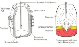
The pig iron contains unwanted accompanying elements such as carbon, silicon, sulphur and phosphorus. These components are removed in a so-called oxygen steel converter through the injection of oxygen, whereby the impurities are oxidised and floated on the liquid metal bath in the form of slag.
The blowing process lasts about 20 minutes and generates a lot of heat. The converter is therefore charged with up to 25% scrap in order to cool down the reaction heat. The addition of lime supports slag formation. After completion of the blowing process, the slag and pig iron are separated by tapping the convertor. The converter is tilted into the tapping position for this purpose. The melt is guided into a steel ladle via the tap hole. The slag is retained in the converter and subsequently re-utilised.
The largest converter vessels worldwide currently contain up to 400 tonnes of crude steel. In addition to the pure oxygen top-blowing process (LD converters), converters with blowing from below (OBM converters) or with combined blowing from above and below (K-OBM converters) are also used nowadays. Inert gases, acting as stirrers, can be inserted from the bottom or the side walls during the blowing process to improve mixing in the converter vessel.
Crude steel production in the electric arc furnace
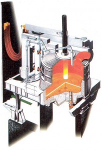
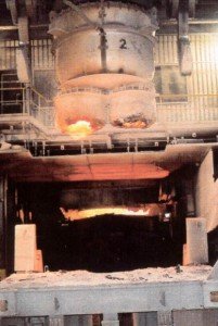
Steels based on scrap are melted in electric arc furnaces. The electric arc converts the electrical energy into heat for melting very efficiently and with a high energy density. Apart from scrap, charges can also consist of sponge iron (DRI or HBI) and/or liquid or solid pig iron. Basically, any type of steel can be produced via the electric arc furnace route.
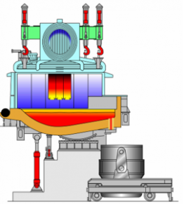
Graphite electrodes conduct the electricity and generate the electric arc.
The main components of the electric arc furnace are the furnace vessel with the tapping bay and work access opening, the removable cover with the graphite electrodes, and the tilting system. The furnace vessel has a refractory lining. The cover is lifted and swivelled to the side to allow filling of the furnace. The scrap is transported over the furnace in scrap baskets that are emptied into the furnace. Then the cover is replaced, the electrodes are lowered and the electric arc ignited on the cold scrap. During the melting process, temperatures of up to 3500°C are created in the arc and up to 1800°C in the steel melt. Additional injection of oxygen or another fuel-gas mixture accelerates the melting process. The furnace is tilted to empty the contents into the steel ladle once the desired chemical composition and steel
We differentiate between DC and AC electric arc furnaces. In general terms, the AC furnace is considerably more efficient than the DC furnace. The latter offers advantages regarding lower circuit feedback, lower noise levels and lower electrode burn-off. The disadvantages lie in the need for operation with a “hot heel” and the more complicated maintenance of the electrodes.
In terms of size and performance, an enormous range of furnaces are used. The smallest electric arc furnaces have tapping weights of 5 tonnes of crude steel and are operated in the foundry industry. The world’s largest electric arc furnaces in the steel industry have tapping weights of 300 tonnes with annual production of 2.6 to 2.8 million tonnes of crude steel. This corresponds to the production capacity of medium-sized basic oxygen steelmaking plants. Depending on the size and configuration of the furnace, energy consumptions of 350 kilowatt-hours per tonne of crude steel with tap-to-tap times of 40 minutes and electrode consumption of 1.1 kg per tonne of crude steel can be achieved nowadays.
Secondary metallurgy: fine-tuning the steel
The high demands made of modern steels necessitate a subsequent treatment of the melt made available in the steel ladle. This applies for both the oxygen converter and the electric arc furnace routes. The main aims of this secondary metallurgical treatment are to adjust the chemical composition of the finished steel, as well as its casting temperature and purity level. Whereby it is necessary to differentiate between the following tasks:
- alloying,
- homogenisation of the melt,
- deep decarbonisation,
- desulphurisation,
- degassing,
- deoxidisation, and
- removal or conditioning of non-metallic inclusions.
Like the range of materials, the metallurgical tasks for the basic oxygen steelmaking plant and the electric steelworks are similarly varied – with comparably complex secondary metallurgical treatments.
Secondary metallurgical process routes: potential treatments
Improved steel qualities with increased flexibility of the metallurgical plants are general trends in secondary metallurgical treatment. For this reason, the further improvement of steelworks logistics remains a permanent task. The number of secondary metallurgical aggregates and plants in the steelworks continues to rise. At the same time, the functionality of the aggregates is increasing – in order to be able to meet the demands for new qualities and works flexibility
Steel in flux: casting the steel
The still-liquid steel produced in secondary metallurgy is cast and solidified for subsequent further processing. About 96 per cent of the liquid steel in Germany now undergoes a continuous casting process – this figure is about 93 per cent worldwide. The rest is cast in so-called ingots. In material flow terms, casting operations in an iron and steel mill are located after the steelworks and before further processing operations, the rolling mill or forging plant.
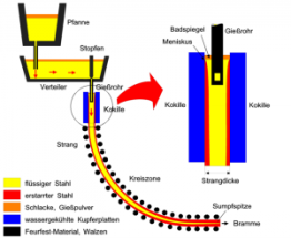
In continuous casting the liquid steel is transported from the pouring ladle to a water-cooled mould via distribution troughs. The shape of the mould determines the format of the strand. As a result of its liquid core, the strand must be cooled with water or a water-air mixture until it has solidified completely. The strand is supported by rollers in order to prevent any bursting out of the strand shell. The intensive cooling leads to an evenly solidified structure with favourable technological properties. After hardening, the strand can be divided into the desired lengths by means of a cutting torch or shears.
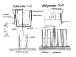
In ingot casting the casting moulds (described as ingot moulds) are filled with liquid steel via a fireproof system of channels either, most commonly, from below or, in rare cases, from above. The steel solidifies in the moulds. After the steel has solidified, the moulds are stripped (i.e. separated from the solidified block) using a crane. The steel can then be further processed in a rolling mill or forging plant. Common formats are round, square or polygonal blocks. Block weight can vary between 50 kg and 600 tonnes.
Ingot casting is mainly used for special steels in small quantities, semi-finished products for profiles with large cross-sections (for the forging industry), slabs for thick sheets, roller bearing and tool steels, fully austenitic steels and steel grades that are not sufficiently mastered in continuous casting.
Unlike ingot casting, continuous casting technology is designed for mass production. The possibility of sequential casting (the casting of several ladles in succession using a set of moulds) permits maximum plant capacity utilisation.
On the track of the perfect steel
In addition to a wide range of customer-specific steel grades, the European steel industry produces about 2,500 standardised steels. The compositions of about 100 steel grades are adapted to the increasing requirements every year. Up to 30 completely new steel grades are developed annually. Whereby – from the targeted adjustment of steel compositions, through the control of production processes, to proving that customer specifications have been met – the use of analytical processes plays a major role.
In system alliances with suppliers, scientific institutes and customers, the collaborating partners exploit shared knowledge and their differing competences and continuously expand their expertise. Germany has a unique steel research and development network. Whereby technical colleges and universities play just as important a role as institutes, e.g. the Max Planck Institutes or the Fraunhofer Society.


